
Third Transmission
The third transmission contains details for VBS2Combined Arms about the type of target, ammunition to use, how and when to engage the target. The observer does not have to enter information into all the data fields. VBS2Combined Arms will use default values for fields with no entries. For example, if no ammunition is selected, then shell high explosive and fuse quick will be fired.
Note:
A selected target shape [Circular, Linear, and Rectangular] within Target Description-> Target Shape, has to be transmitted for the mission to be completed.
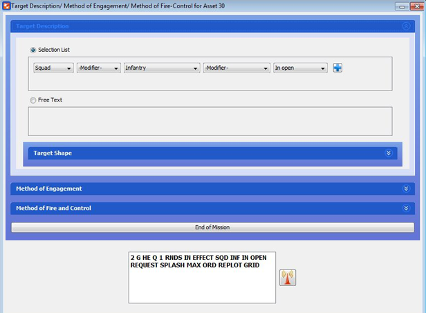
∆ Image 4g: 3rd panel window |
- Target description: This is used to convey to the guns what it is they are firing at. It will affect the rounds and the fuses used by the guns. The observer may specify three attributes of the target; these are size, type, and status. By clicking the additional button, the observer may send several separate descriptions of the target. This will add an additional line in the GUI.
- Selection List
- Size. This specifies the size of the unit and can be the unit size (such as Sect, Pl, and Bty etc.) or a numerical number.
- Modifier. This specifies a whether the object being fired is reinforced
- Type. This specifies a type of unit or object being fired at, for example, it could be infantry, armoured, buildings, trucks, rotary wing etc
- Modifier. This specifies whether the object being fired at contains small arms, RPG, MG, machine guns or is a convoy
- Status. This describes what the target is currently doing and how well defended it is likely to be from artillery. Examples include moving, in open, dug in no OHP, dug in OHP, under cover etc
- Additional. When this button is clicked, new selection list is created
- Free Text: This is used to specify the target descriptions via text entry. When the first character of a word is typed in, a list of possible target descriptors will be listed down. The appendix section of this user document contains Target Description Grammar and tokens. Any word within <> should be mapped with tokens.
- Target Shape: This is used to specify how big the footprint of the target is on the ground. The observer should select the option that most closely resembles the unit’s geographic position from the options Circular, Rectangular, and Linear.
- Circular. Specify the radius of the circle which would surround the target.
- Rectangular. Specify the length and width of the target and the attitude of the target (mils). Note, if the length is five times greater than the width of the target, it is usual to describe the target as a linear formation, rather than rectangular.
- Linear. Specify the length of the target (m), and the attitude of the target (mils).
- Selection List
- Method of Engagement.. Specify details on how to engage the target.
- Type of Adj.Observer can select area (default) for area targets. Select precision for one weapon engaging a point target.
- Trajectory. Drop-down box allows the observer to specify the trajectory of the rounds. By default the box is blank and in most cases, this will result in a low angle trajectory (default) for artillery and naval gun fire, high angle must be requested for these firing units. High angle is default for mortars .
- Distribution. Would be the pattern of bursts in the target area.
- Circle. When selected, observer will define a radius. During the fire for effect phase, all rounds will impact along the perimeter of the defined circle.
- Converged. All rounds will impact the same point.
- Parallel. This is where the impact of rounds mirror the physical layout of the guns on the ground.
- Open. Guns will fire along a line of fixed length. The line will be perpendicular to the GT line.
- Range. Used with illumination missions. One round is fired over the target and a second round is fired short as the observer looks at the target.
- Lateral. This is used predominently for illumination. It results in rounds falling left and right of the target from the observer’s perspective.
- Range and Lateral. Used with illumination missions. Fires 4 rounds, one over, short, left and right as the observer looks at the target.
- Special. The distribution can be specified. The length, ATT (direction of the distribution with respect to north) and width can be specified. Normally used with illumination missions.
- Guns Adjust and Guns FFE.Observers are able to select
ammunition and fuses for the guns to fire in specific phases. Type of
ammunition to fire in the adjust fire phase and/or specific ammunition for
the fire for effect phase. Relevant parameters will appear for certain
ammunition and fuse choices.
- i. The ammunition and fuses chosen here will affect the type of round fired later in the mission, unless this rounds type is specifically overridden by a subsequent call-for-fire transmission. .
- The round types available are:
- HE: high explosive
- WP: white phosphorus canisters
- Smoke: white phosphorus shell
- DPICM: Dual Purpose Improved Conventional Munitions (bomblets)
- APICM: Anti-Personnel Improved Conventional Munitions, (land mine)
- CPHD: Copperhead, laser guided precision munitions
- EXCALIBUR: precision munitions
- ILLUM: Ammunition type used to illuminate a specific area, the burn duration and the rate of fall depends on the calibre type.
- Fuse Selection. As well as selecting the ammunition type, the Fuse may also be specified. Any fuse may be chosen for any ammunition type; however, some fuse / ammunition type combinations will be ineffective. For example, using DPICM round with a Quick fuse will cause minimal damage in the impact area. The options for fuses are:
- Quick. This is a point detonating fuse. There are no
parameters to specify with this fuse selection.
Note:
In a FFE scenario with MLRS if the fuse is selected as Quick, and the ammunition is not selected, it should always fire HE. Whereas when the Timed fuse is selected it should fire DPICM. The number of rounds will be as selected or else default which is 3 rounds. - Timed.This is a fuse that will explode a certain number of seconds after being fired. The fuse time is specified in meters above sea level. When this value is specified, the FDC / Bty GPO will conduct the ballistic analysis and will turn that distance into a time of flight. The guns will then use this time of flight to ensure that the rounds detonate at the correct moment.
- Variable Time (VT).This fuse will explode the round
when it is a specified distance from the ground. The round has a sensor
at the front that is able to use Doppler shifting to determine how far
it is from the ground (or building or other object). VBS2Combined Arms will
detonate the round if it ever passes closer to the ground than the
specified fuse setting. Normally this value is several meters (7m-15m);
however, VBS2Combined Arms does not restrict the value of this fuse
setting. The parameter specified for a VT fuse is in meters above ground
level.
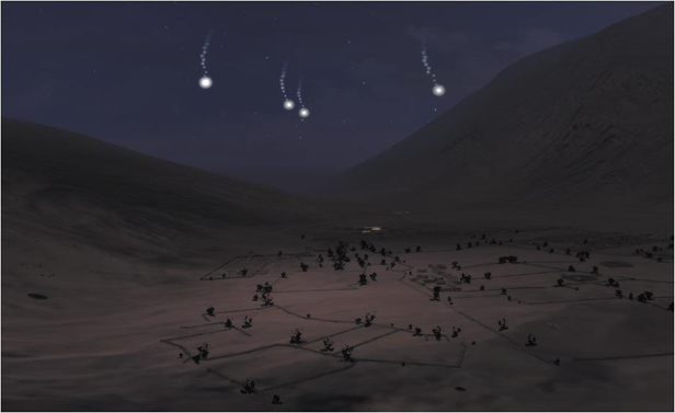
∆ Image 4j: VBS2 3D night-time environment explosion
- Delay. A delay fuse is similar to a quick fuse; however, it will wait .05 seconds before exploding once it has impacted. There are no parameters to specify with this fuse.
- Quick. This is a point detonating fuse. There are no
parameters to specify with this fuse selection.
-Window.png)
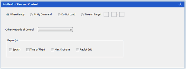
∆ Image 4h: 3rd Panel (Method of Engagement) Window
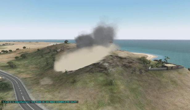
∆ Image 4i: VBS2 3D daytime environment explosion
- Method of Fire and Control.. Specify details
when to engage the target.
- a. Fire. The default order for opening fire is for the guns to fire when ready, once they have received fire mission. However, the observer may choose to issue an At My Command (AMC), Do Not Load or Time on Target (TOT) order at this stage
- When Ready - [Default Order] Once the fire mission information is received, the guns will open fire.
- At My Command - If AMC is selected then the guns will not fire until they receive the command ‘Fire’ from the observer after the user has sent the execution information. The “Fire” button is active in the fourth transmission panel within the “Subsequent Changes”.
- Time on Target - If TOT is ordered, a text field will become enabled. Here, the user can enter the time that they require the rounds to land at the target. This time is based on the simulation timer which can be viewed in the simulation window.
- Do Not Load - If DNL is ordered, then the guns will not fire until they receive the cancel DNL order from the observer.
- a. Fire. The default order for opening fire is for the guns to fire when ready, once they have received fire mission. However, the observer may choose to issue an At My Command (AMC), Do Not Load or Time on Target (TOT) order at this stage
- Replot(s)
- Splash .Will display a radio message 3 seconds before impact.
- Time of flight .The time from the firing unit to the target location.
- Max Ordinate .The max altitude from sea level the round will travel.
- Replot Grid .The impact location of the round.
- Other Method of Control.
- Coordinated Illumination – The delay in seconds once this option is selected will be when the illum fuse explosion is the brightest.
- Continuous Fire – Once the firing time duration & the firing rate are specified then continuous FFE rounds can be fired.
- Continuous Illumination – First a FFE is fired, then an adjustment is made in the fourth transmission panel, to send a CONT ILLUM, where a continuous ILLUM shots are fired with the delay.
- Can’t observe – A ‘Can’t observe’ message is sent to the observer from the gunline.
- By Round At My Command - Rounds are fired when the AMC is selected and mission is transmitted in the Adjustment Panel.
Laser Guided Munitions. If ammunition copperhead is selected, observer can enter a PRF code for the round. Standard radio transmissions will be used when controlling this type of round.
Step 1: After the call for fire is transmitted, if copperhead is selected, VBS2Combined Arms will report the time of flight, angle T and if the round is approaching from the left or right side of the observer target line.
Step 2: Once fired, VBS2Combined Arms will prompt the observer when to activate the laser designator and paint the target.
Step 3: As long as the laser designator is in the ON position, the round will make corrections to impact the laser spot. If the round is unable to impact the spot, the round will continue on a regular ballistics’ path.
∆ Image 4k: Third Transmission panel (Method of Fire and Control) window |