Fire Mission Data
To start a fire mission from the Instructor Control Panel one or more trainees should be connected to the Instructor. The Instructor can select the Firing Unit, Observer, and the Mission Type from the drop down lists labelled respectively as Firing Unit, Observer and Msn Type. .
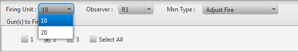
∆ Image 5b: Firing unit/ observer/ mission type |
Note:
A validation is carried out for gun selection, if no guns are selected a warning message will pop up.
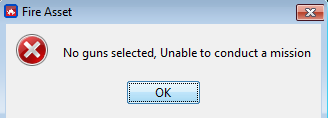
∆ Image 5b2: Warning: No guns selected |
The guns to be allocated in the fire mission can be selected by ticking the checkbox for the respective gun, or else all the guns can be allocated by selecting the ’Select All’ option.
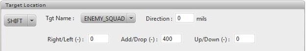
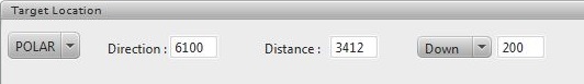
The users can enter the target location, altitude, and direction as preferred for the fire mission type which could be a GRID, SHIFT, or a POLAR mission.
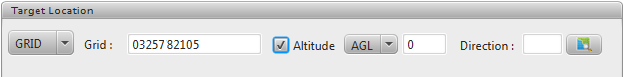
∆ Image 5c1: Target Location |
∆ Image 5c2: Target Location |
∆ Image 5c3: Target Location |
Note:
The instructor marker on map:
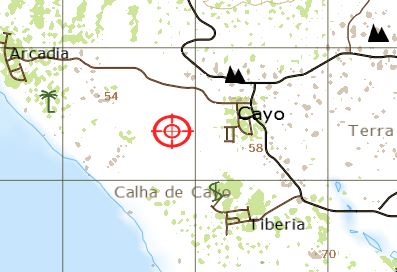
∆ Image5c4: Instructor Marker on map |
The instructor marker in 3D:
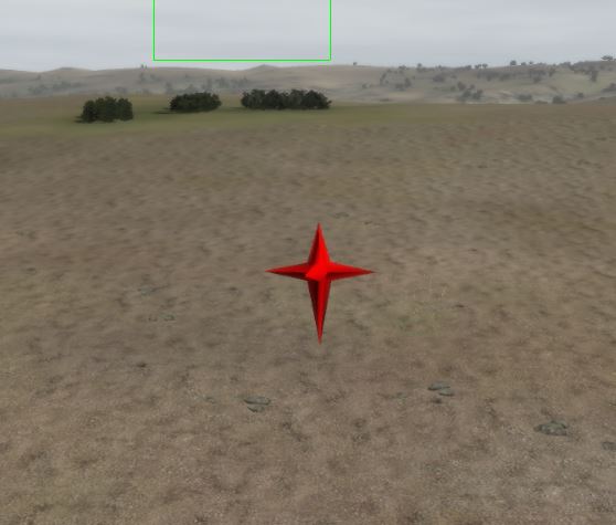
∆ Image5c5: Instructor Marker in 3D |
The users can then select the target descriptions, shell/fuse combinations, distribution of the shot, and finally the method of fire. The users can select different combinations of ammunition for the fire mission with the help of the With button. The With button will be enabled only if the users select 2 or more guns for the fire mission. User can select minutes or seconds for total duration. Default total duration would be 20 seconds and rate is 3 Rds/min.
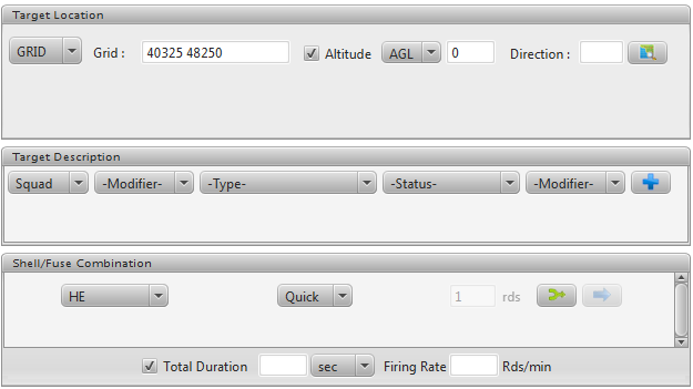
∆ Image 5d1a: Fire Mission Details |
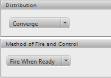
∆ Image 5d1b: Fire Mission Details |
If Fire For Effect is selected as Msn Type, Followed By Rounds are also made available in Shell/Fuze Combination allowing a mission to be constructed with many rounds to fire different ammunition and fuse types. For each Followed By Round, a separate serial will be created in the Serial Table for the mission.
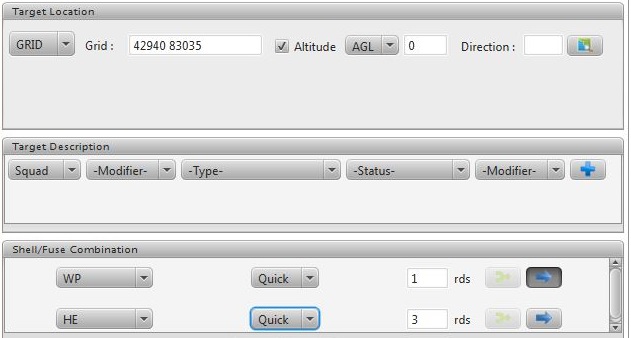
∆ Image 5d.2: Fire Mission Details |
If a user need to enter more details for the CFF mission such as the target size, method of adjustment, it can be achieved by clicking on the ‘Advanced’ button.
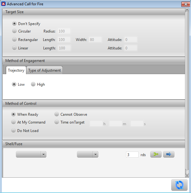
∆ Image 5e: Advanced call for fire |
After selecting the relevant advanced descriptions and clicking the ‘Update’ button will update the CFF mission details in the Instructor Control Panel main window. If ammunition values are already selected from Instructor Control Panel main window and no ammunition values have been selected from the ‘Advanced Call for Fire’ window, VBS3Fires will use the initial values entered in Instructor Control Panel.
After all the details relevant to conduct the fire mission are entered, the users can click on ‘Validate’ button to view the gun details. This will show the details of the mission which will be conducted such as the deflection, quadrant, shell, fuse, and fuse setting.
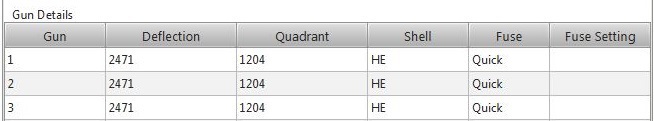
∆ Image 5f: Fire Mission Data tab |
The user can press the fire button to conduct the fire mission, where the guns will be laid and the shots will be released to the target location
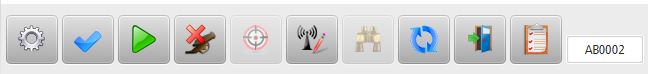
∆ Image 5g: Button Panel |
Note:
In a multiple instructor scenario if an instructor allocates a fire asset for a fire mission, upon clicking ‘Execute’, the particular fire asset is locked by that instructor. The fire asset is unlocked once the instructor clicks ‘End of Mission’.
Whenever a mission is conducted via the Instructor Control Panel there will be no radio messages shown in the Radio Log other than for an Error Messages. If the instructor requires to send messages to the trainees connected to VBS3Fires press ‘Send MTO’ button and enter the necessary message and click ‘Ok’. This will send a message to the selected observer giving the details of the fire mission. According to the option selected in Preferences → Instructor Control Panel → Message To Observer, the instructor may or may not grant the authority of deciding whether to fire or not to trainee.
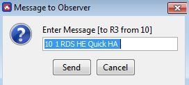
∆ Image 5h1: MTO message to observer window |
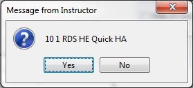
∆ Image 5h2: MTO message requesting for acknowledgement from trainee |
∆ Image 5h3: MTO message from Observer to Trainee |
∆ Image 5i: Serial table |
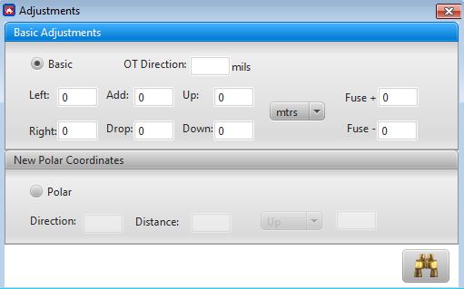
If an Instructor wants to process an adjustment, to an active fire task, select the battery entry of that fire task and then click the ‘Adjust’ button. Then an ‘Adjustments’ window will be opened. Perform the adjustments, and click ‘Adjust’ button. Then click ‘Add’ button to confirm the changes to the battery entry. Polar adjustments can be achieved by adjusting the direction and distance values of that had just been fired. Then the range (Distance) and direction are sent to the battery. The user has to select the required serial which needs to be adjusted from the serial table and then do the adjustments.
The check fire button will stop all firing during multiple round missions. Button will change to Cancel check fire, click to continue firing.