NATO Call-For-Fire
Step 1: Set VBS3Fires doctrine in Toolbar > Options > General Settings > Doctrine Tab > select 'NATO', then click 'Save'. After saving the doctrine, all missions will use the US Army/USMC format. Perform this step if using a new VBS3Fires install.
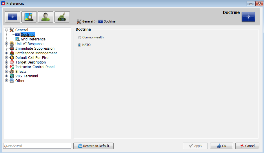
∆ Image M9: VBS3Fires Preferences Window |
Step 2: The following windows are optional but provide an instructor or controller additional information on a mission. The radio log will list all messages to and from VBS3Fires and the observer. (Toolbar > Radio > Radio Log). Projectile analysis will list all rounds fired by VBS3Fires (Toolbar > Analysis > Projectile). These windows can be repositioned within the VBS3Fires workspace.
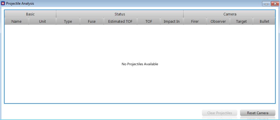
∆ Image M10a: VBS3Fires Projectile Analysis window |
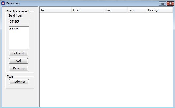
∆ Image M10b: VBS3Fires Radio Log window |
Step 3: Start a new mission, Toolbar > Fire Mission > New Fire Mission to open the first transmission window. Select firing asset ‘20’, select type of mission ‘Adjust Fire’ and method of target location ‘GRID’ (optional) and click the ‘Transmit’ button.
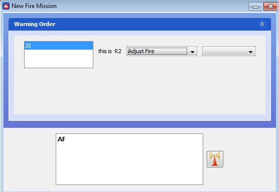
∆ Image M11: Call-For-Fire (NATO) VBS3 Fires Warning Order |
Note:
Once you clicked the transmit button, new entries
will appear in the 'Radio Log' window. There are two transmission entries made
in the radio log. One is the transmission from the observer to fire asset and
the other is the response from the fire asset.
Step 4: The second transmission 'Target Location' will open. Enter the grid value of the target '10888554' and click the 'Transmit' button.
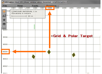
∆ Image M12: The Grid and Polar Target label in the RTE View |
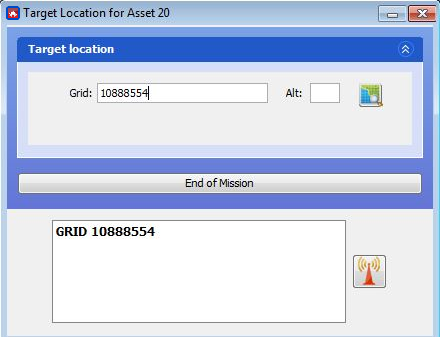
∆ Image M13: Call-For-Fire (NATO) VBS3 Fires Entering the Target Location |
Step 5: The third transmission 'Target Description/Method of Engagement/Method of Fire Control' will open. At a minimum, must enter a target description and click 'Transmit' button. Target description can be entered using the drop down menus or free text..
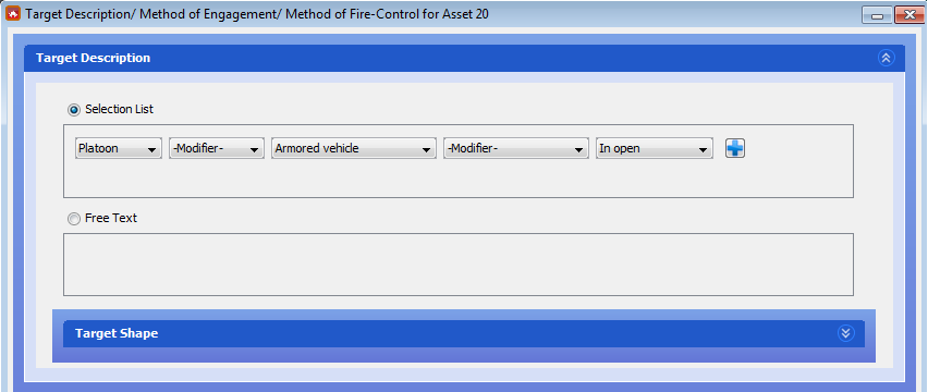
∆ Image M14: Call-For-Fire (NATO) VBS3 Fires Target Description & Shape |
Note:
Missions cannot be processed unless a target
description is entered
Step 6: VBS3Fires will calculate the firing data. In the Radio Log window, all message traffic will be displayed, in Projectile Analysis a list of rounds fired will appear.
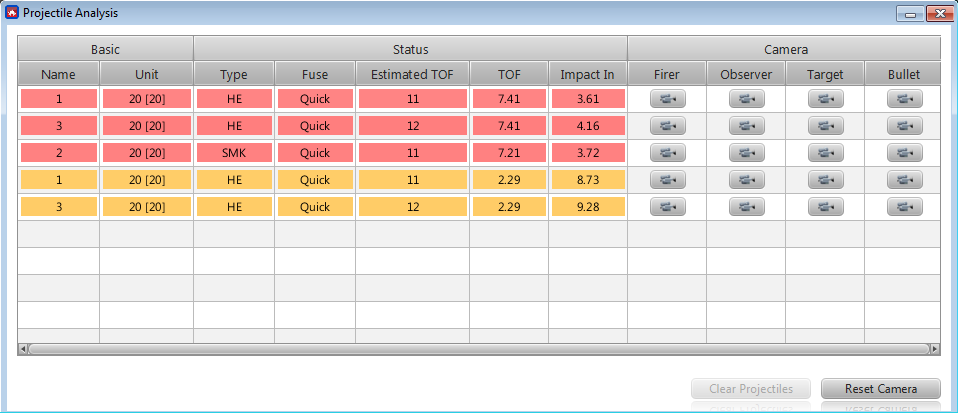
∆ Image M15a: Call-For-Fire (NATO) VBS3Fires Projectile Analysis Window |
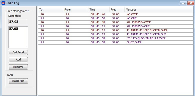
∆ Image M15b: Call-For-Fire (NATO) VBS3Fires Radio Log Window |
Messages and projectiles that are highlighted YELLOW have been transmitted or fired within 15 seconds. In the Projectile Analysis window, rounds will be highlighted RED 5 seconds to impact. RED TEXT means round has impacted.
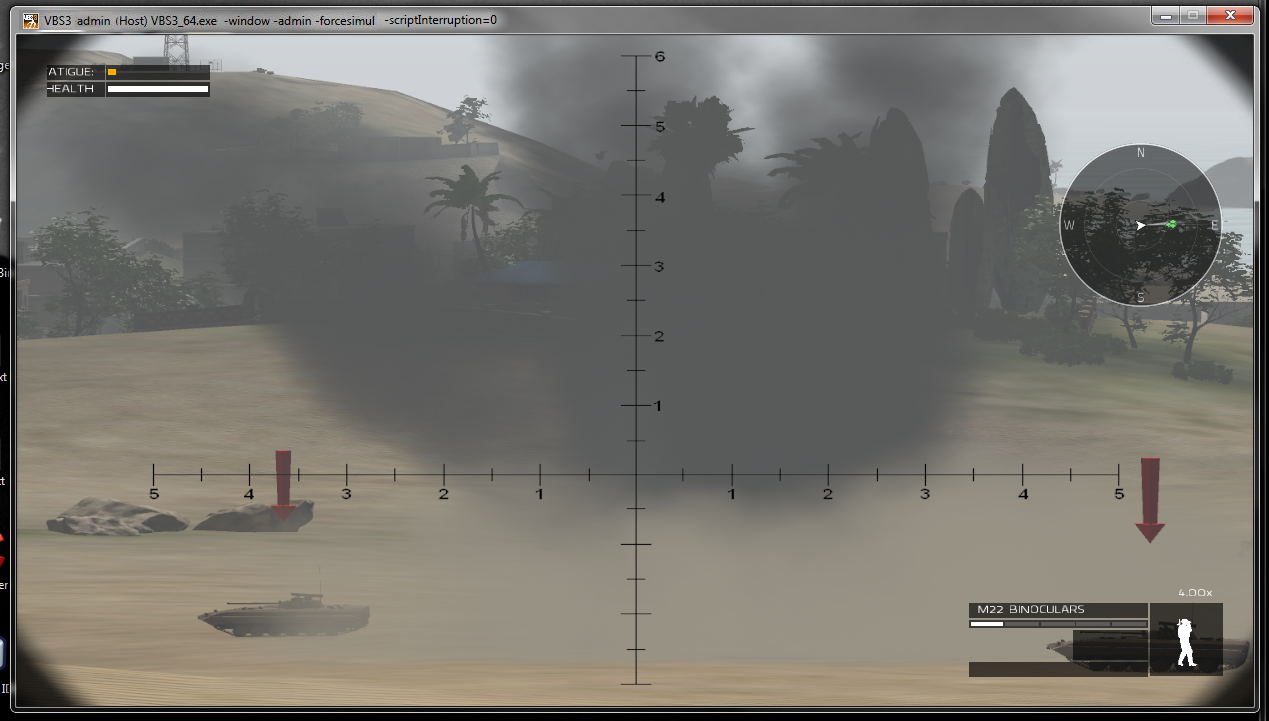
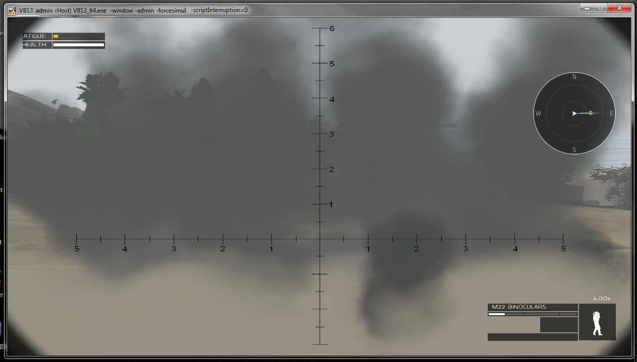
∆ Image M16: Call-For-Fire (NATO) Adjust Fire mission |
Step 7: Enter corrections for your mission. Observer can enter Observer to Target direction, Left/Right, Add/Drop, or Up/Down adjustment. In addition, the observer can change the mission from Adjust Fire to Fire For Effect. Left, Drop, and Down corrections must start with a (-) negative sign
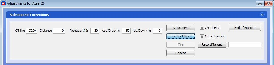
∆ Image M17: Call-For-Fire (NATO) corrections |
∆ Image M18: Call-For-Fire (NATO) Fire for Effect |
Step 8: To end the fire mission, click "End of Mission" button and then click 'Transmit" button. Alternatively, you can type 'EOM' at the bottom of any transmission window.
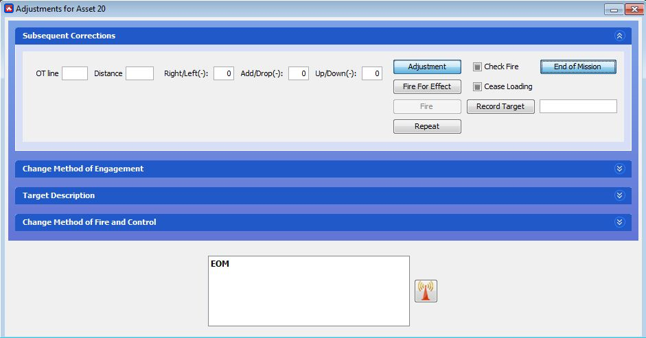
∆ Image M19: Call-For-Fire (NATO) End of Mission |